

The Architect's Guide to MVHR: Designing Heat Recovery into Modern Homes

Modern homes are built tight. Insulation is thicker, junctions are sealed, and the air leakage that once ventilated a house by accident has been designed out. That is good news for energy bills — and a real problem for air quality, unless ventilation is designed in deliberately. This is why MVHR (mechanical ventilation with heat recovery) has moved from a specialist add-on to a core part of modern residential design — and why it now belongs on the architect's drawing board, not the installer's van.
Why airtight homes changed the brief
A family of four releases litres of moisture into the air every day through cooking, showering and simply breathing. In a leaky building that moisture escapes through the fabric. In an airtight one it accumulates — along with CO₂, VOCs and odours — and shows up as condensation, mould and stale rooms.
UK Building Regulations recognise this. Approved Document F treats continuous mechanical supply and extract with heat recovery as a recognised whole-dwelling ventilation strategy, and Approved Document L rewards it: recovering heat from extract air feeds directly into SAP calculations and the home's energy performance. Once a design targets an airtightness of around 3 m³/(h·m²) at 50 Pa or better — standard territory for new builds heading toward the Future Homes Standard, and essential for Passivhaus — trickle vents and intermittent fans are no longer a credible answer. MVHR is.
How the system actually works
An MVHR unit continuously extracts warm, humid air from kitchens, bathrooms and utility rooms, passes it through a heat exchanger, and supplies fresh, filtered air — pre-warmed by up to ~90% of the recovered heat — to living rooms and bedrooms. Air moves gently and constantly, rather than in noisy bursts.
The decisions that belong at concept stage
MVHR fails as an afterthought. Retrofitting duct routes into a finished design produces long runs, tight bends, boxed-in bulkheads and noise. Designed early, the same system disappears. Three decisions matter most, and all three are spatial:
- Where the unit lives. It needs roughly a tall-cupboard footprint, a condensate drain, an external wall or roof nearby for intake and exhaust, and service access for filter changes — a utility room, plant cupboard or insulated loft all work.
- How the ducts travel. Short, straight, rigid runs beat long flexible ones on pressure drop, noise and fan energy. Agree ceiling void depths, joist directions and riser positions with the structural design, not against it.
- Where air enters and leaves each room. Terminal positions drive comfort (no draughts across beds and desks), acoustics and — the part most guides ignore — what the ceiling actually looks like when the builders leave.
The numbers worth knowing by heart
- Duct connections of 100–200 mm cover most domestic branch runs; size for low velocity to keep the system silent.
- Heat recovery efficiency around 85–90%+ on good units — the figure SAP rewards.
- Airtightness of ~3 m³/(h·m²) @ 50 Pa or better is where MVHR becomes the default answer rather than an option.
- Continuous background rates with boost for cooking and bathing, commissioned and recorded room by room — a Part F expectation, not a nice-to-have.
Acoustics: design it quiet
Noise is where MVHR reputations are lost. Three design moves keep it inaudible: keep duct velocities low; isolate the unit from the structure; and fit acoustic plenum boxes at terminals so fan and cross-talk noise die before they reach the room. Plenums also equalise pressure across the terminal face, which makes the airflow itself quieter and more even. On projects with bedrooms stacked over living space, treat the plenum as standard, not an extra — our acoustic plenum range exists for exactly this.
The visible 1%: terminals are an architectural surface
Ninety-nine percent of an MVHR system hides in voids and risers. The one percent you see — the supply and extract terminals — lands in the most looked-at surface of every room: the ceiling. A beautifully resolved interior finished with a ring of white plastic in each room is a detail nobody drew.
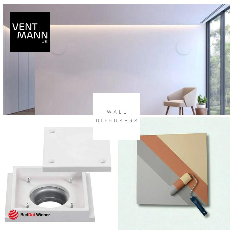
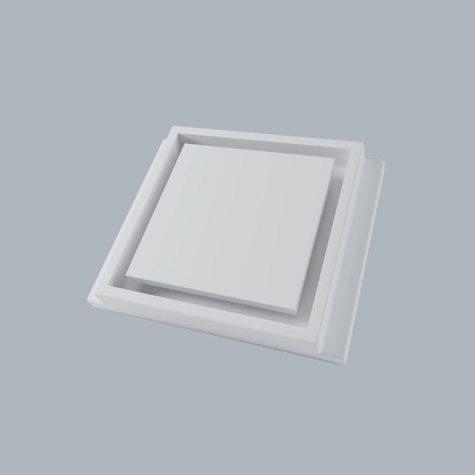
This is where terminal choice becomes an architectural decision. Frameless plaster-in diffusers are made from gypsum, set into the plasterboard, skimmed at the edges and painted with the ceiling — leaving only a clean slot. Supply and extract share the same language in every room, the finish accepts any colour, and airflow is engineered around the Coandă effect, so supply air hugs the ceiling plane and mixes evenly instead of dumping cold streams into the room.
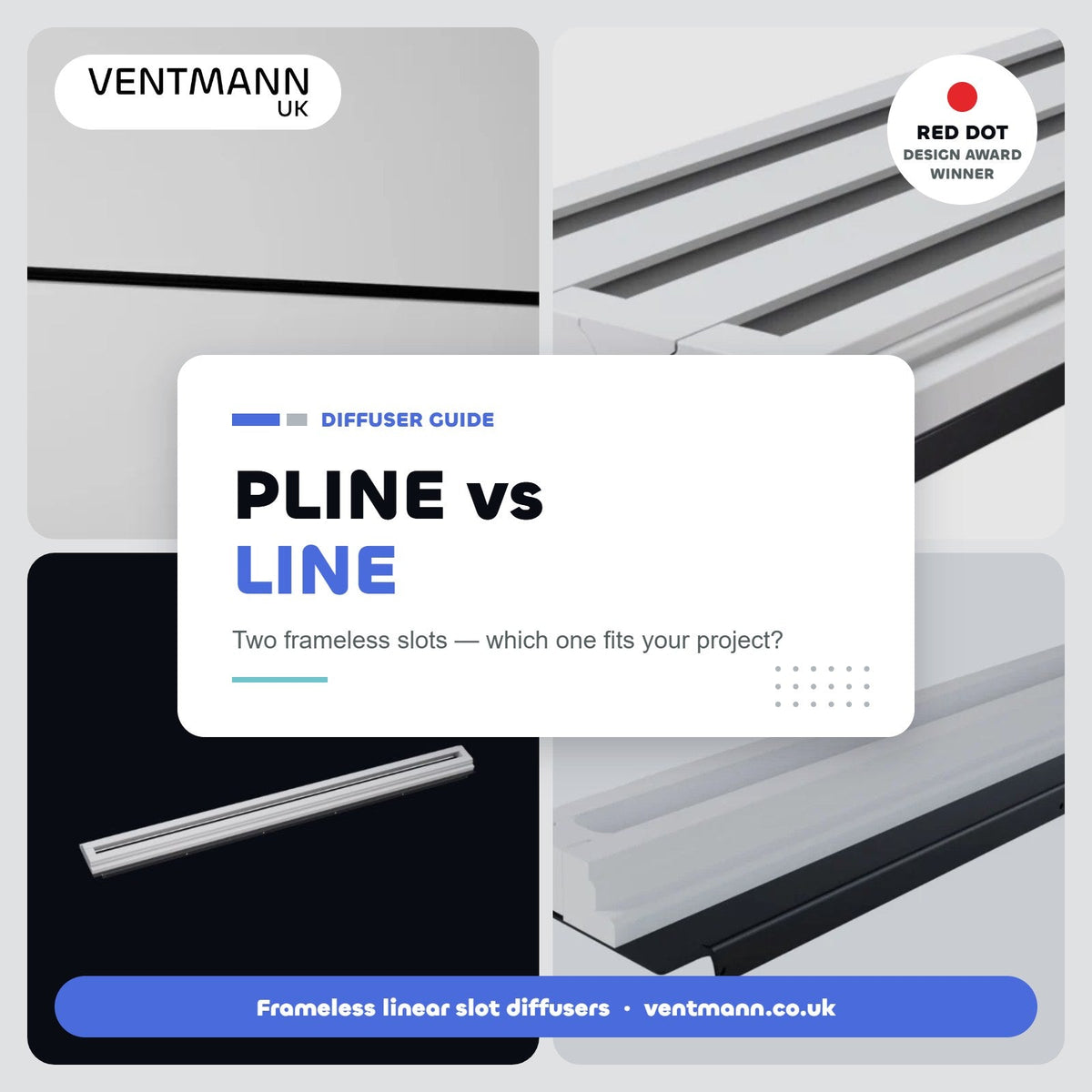
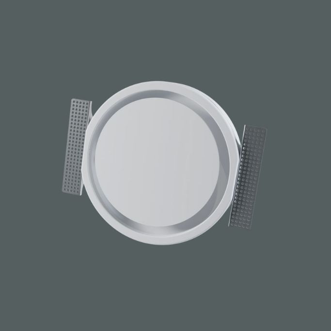
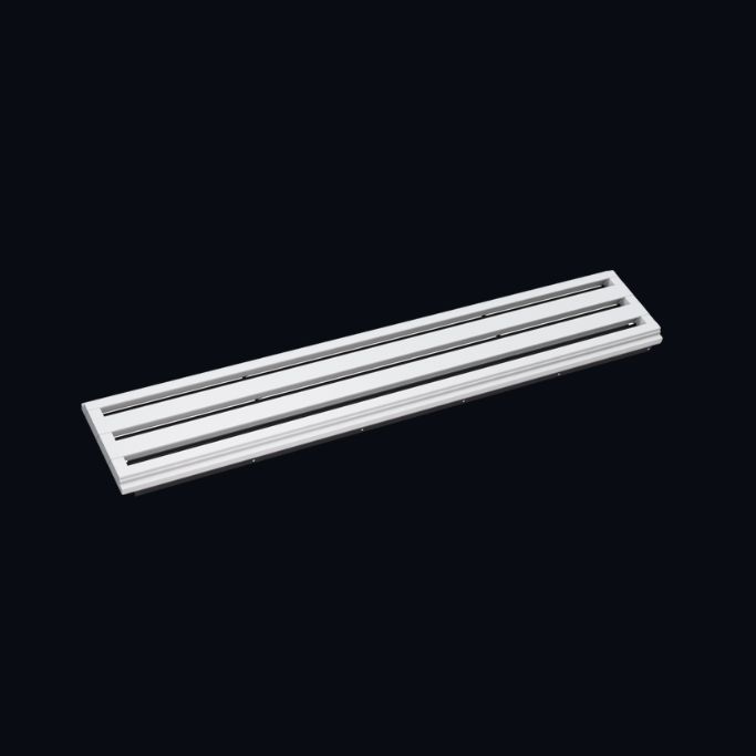
Specifier's shortcut: the Performance Circle (100–200 mm spigots, up to 300 m³/h) covers circular terminals; Line diffusers handle continuous shadow-gap details. Both ship with Revit BIM objects (.rfa), published airflow and pressure-drop data, and step-by-step installation guides your drylining crew can follow without a specialist trade.
An architect's MVHR checklist
- Name the ventilation strategy at Stage 2–3 and reserve the plant space and riser on the first plans.
- Coordinate duct zones with structure before anyone draws a bulkhead.
- Fix the airtightness target early — it decides whether MVHR is optional or essential.
- Schedule terminals room by room: supply to habitable rooms, extract from wet rooms, sized from airflow calculations rather than habit.
- Specify acoustic plenums where silence matters — which in housing is everywhere.
- Decide what the terminals look like while the ceiling is still yours to design.
- Commission properly: measured, balanced, recorded flow rates at handover.
Design the ventilation in. Then make it disappear.
Send us your plans and we'll size every terminal on the system — free airflow calculations, published technical data, BIM objects for Revit, and frameless gypsum diffusers delivered next-day across the UK. There's also a CPD course on architectural ventilation for your practice.
Get Free Airflow Calculations Open the Product Selector
Call 01283 240025 · Email sales@ventmann.co.uk