



BIM and Coordination: Getting Diffusers Into the Model Early
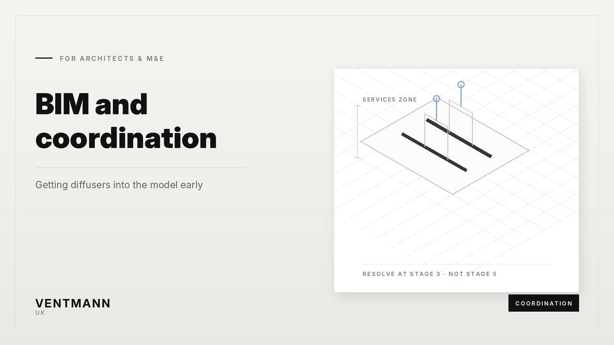
A frameless diffuser is not a terminal you hang off the end of a duct run. It is a hole in the architect's ceiling, a plenum in the structural zone, a fixing on the soffit and a sequencing constraint on the boarding. If it enters the model at Stage 5 it is a clash. If it enters at Stage 3 it is a detail. This is what to put in the model, when, and who owns each part of it.
The core point
A metal grille is coordinated after the ceiling exists. A gypsum diffuser is part of the ceiling. The model has to reflect that, and the first team to feel it is architecture, not M&E.
Why late entry hurts so much more than with a conventional terminal
With a lay-in grille, a late change costs a different tile. With a plastered-in gypsum diffuser it costs a cut ceiling, a re-skim, a re-decoration and a programme hit, because four things are already fixed by the time anyone notices:
- The void depth. A top-entry GTG plenum needs clear space above it to turn a duct onto the spigot. If the zone has been compressed to 200 mm by the time services are modelled, the answer is a side-entry VTBOX — and that changes the branch layout, not just the box.
- The soffit fixings. The plenum hangs from the structure above on proprietary fixings, set to a height that puts the diffuser face exactly at finished ceiling level. That is a dimension derived from the architectural model, not the services model.
- The boarding sequence. The diffuser and plenum go up before the main plasterboard sheet, which is then cut and lifted to meet the diffuser face. Boarding cannot proceed past a position that has not been resolved.
- The reflected ceiling plan. Slot positions interact with lighting runs, sprinkler heads, detectors, shadow gaps and joint lines. All of those are architectural decisions that get locked early.
What to place, and at which stage
| Stage | What exists in the model | Owned by |
|---|---|---|
| Stage 2–3 · Concept & spatial | Generic slot as a line on the RCP; a reserved services zone depth; a decision that outlets are frameless | Architect |
| Stage 3 · Spatial coordination | Correct family, correct length, correct slot count, plenum body with its real envelope and entry direction | Architect places, M&E sizes |
| Stage 4 · Technical design | Width code, spigot diameter and position, flow rate, hanger positions, boarding interface detail | M&E, with architect sign-off on face position |
| Stage 5 · Construction | Part numbers, pre-assembled sets, installation sequence against the boarding programme | Contractor |
The one row that goes wrong most often is Stage 3. Teams model a placeholder box with no entry direction, coordinate everything else around it, and then discover at Stage 4 that the real plenum cannot be fed from where the branch arrives.
Getting the geometry right
Ventmann publishes BIM objects for the ranges, including the plenum boxes in all three width codes, so there is no reason to model a proxy. Download them from the relevant product page or from the technical catalogue, then check four things when you place them.
1. Host the family to the ceiling, not to a level
The one dimension that must never drift is the relationship between diffuser face and finished ceiling. Host to the ceiling and the face follows a ceiling height change automatically. Host to a level and it does not, and you find out on site.
2. Model the plenum envelope, not the plenum
Clash detection against the box alone passes happily with a duct 40 mm away from the spigot and a bend that cannot physically be made. Add a maintenance and connection envelope above a GTG, or to the side of a VTBOX, so the clash tests catch the connection rather than only the object.
3. Model the hanger zone
The plenum is fixed to the structure above with proprietary hangers. Those hangers occupy the same zone as everyone else's hangers, and they are not negotiable because they set the diffuser face height. Put them in the model at Stage 4.
4. Model the slot as a void in the ceiling
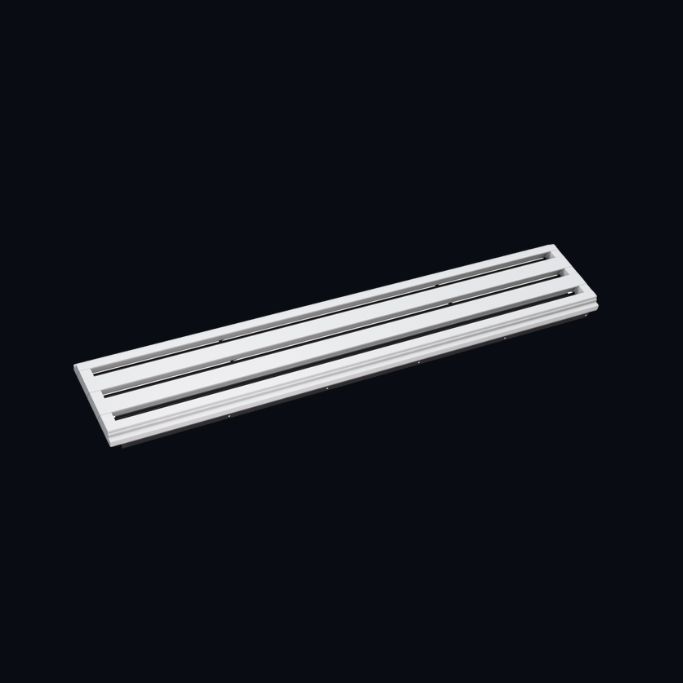
The RCP needs to show the actual visible slot length, which may be shorter than the diffuser body where the magnetic end blocks have been set in. If the model shows the body length and the drawing shows the visible length, the joiner setting out the lighting will use the wrong one.
Parameters worth carrying
Whatever your information requirements say, these are the fields that stop the real arguments. Carry them on the diffuser family and the plenum family both.
| Parameter | Why it matters |
|---|---|
| Range (LINE / PLINE / PCIRCLE) | Different profiles, different performance, same visual footprint |
| Length and slot count | Drives free area, plenum width code and the RCP |
| Plenum width code (A/B/C) | Must match the diffuser; the single most common ordering error |
| Entry direction (top / side) | Decides GTG vs VTBOX and therefore the branch route |
| Spigot diameter | GTG offers Ø75/125/160, VTBOX offers Ø125/160/200 — not interchangeable |
| Design flow rate | Lets the schedule be checked against the selector without opening a spreadsheet |
| Face finish / RAL | Supplied white, painted on site — the decorator needs to know which colour |
| Acoustic or insulated | Carries the reason for the choice into FM, not just the part number |
The clashes that actually bite
In roughly the order we see them raised:
- Plenum versus joist or downstand. A 1250 mm plenum is a long object. It wants a clear run in one direction, and timber joists at 400 mm centres rarely offer one. Either align the diffuser with the joist direction or accept trimming.
- Flexible duct bend radius. The duct clears the box in the model; the installable bend does not. Model the envelope.
- Sprinkler and detector spacing. Moving a slot 300 mm to clear a plenum can put a head outside its coverage. Check both ways.
- Lighting track versus slot line. Not a clash in the model and very much a clash on the ceiling. If the slot and the light line are within about 150 mm and not parallel, it will look like a mistake.
- Hanger versus everyone else's hanger. Especially in shallow zones where cable tray and pipework are already fighting.
Sequencing: the bit the model usually misses
Geometry can be perfect and the installation still fail, because the fitting order is non-standard. The published sequence runs: pre-position the duct in the void; fit temporary battens with plasterboard spacers at the finished ceiling line; fix the pre-assembled diffuser and plenum onto the battens; hang the plenum from the structure and adjust its height until the diffuser face just touches the battens; remove the battens; cut and lift the main plasterboard sheet up to the diffuser; joint, sand and paint.
Read that back as a programme and two things follow. The diffuser must be on site and fixed before the ceiling is boarded — so procurement sits earlier than for a conventional terminal. And a late positional change is not a change to a terminal; it is a change to a ceiling that has already been built. The full sequence is on the Line diffuser installation page and the plenum box installation guide.
Put it in the 4D model, or at least in the programme notes: "architectural diffusers and plenums fixed and set to level" is a hold point before boarding, in the same way a first-fix inspection is. Teams that write it down do not get caught by it.
Who owns what — settle this at the first coordination meeting
| Decision | Owner |
|---|---|
| Position and length of the visible slot | Architect |
| Flow rate, throw, dB(A), pressure drop | M&E |
| Range and slot count (where these conflict) | Joint — this is the real conversation |
| Entry direction and plenum type | M&E, constrained by architectural zone depth |
| Face level and tolerance | Architect, delivered by the drylining contractor |
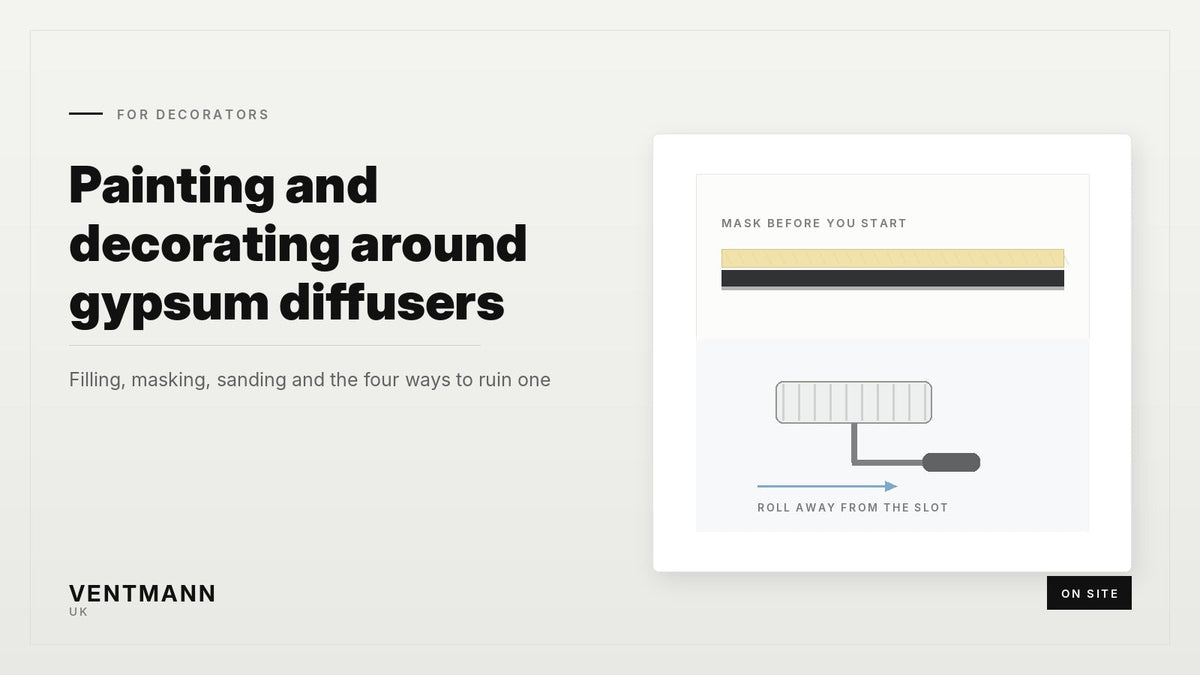
| Paint specification on the diffuser face | Architect — and tell the decorator |
A Stage 3 checklist you can paste into a meeting agenda
- Is the services zone depth confirmed, and does it allow top entry?
- Are the diffusers in the architectural model, hosted to the ceiling?
- Does every diffuser have a range, length, slot count and flow rate against it?
- Does every plenum have an entry direction and a width code?
- Have connection and hanger envelopes been added for clash testing?
- Does the RCP show visible slot length rather than body length?
- Have slot lines been checked against lighting, sprinklers and detectors visually, not just by clash report?
- Is "diffusers fixed before boarding" written into the programme?
Eight questions. Asked at Stage 3 they take twenty minutes. Asked at Stage 5 they take a ceiling.
CPD for design teams
Ventmann runs a CPD session for architects, interior designers and HVAC engineers covering architectural air distribution, frameless diffuser detailing and exactly the coordination issues above. It can be delivered in your office or online — details on the CPD course page.
Coordinating a live project?
Send us the RCP and the services zone section early. We will tell you which positions work with top entry, which need side entry, and what the plenums will actually occupy — before it is expensive to find out.
Request a free quotation · BIM objects & technical catalogue · Book a CPD session