

Sizing a Diffuser From Your Design Rates: Spigot Diameters, m³/h and Slot Count
You have a design rate in litres per second and a ceiling plan. You need a spigot diameter, a diffuser length and a slot count. This is the arithmetic, in order, with the numbers written out — including the one decision people consistently get wrong: when to step up from two slots to three.
Before you start
Ventmann publishes rates in m³/h. UK design rates are usually in l/s. The conversion is the whole of the difficulty: l/s × 3.6 = m³/h. So 15 l/s is 54 m³/h; 30 l/s is 108 m³/h.
Step 1 — Get the rate per outlet, not per room
The design rate is for the space. The diffuser is sized for what passes through it. If a 54 m³/h bedroom supply is split across two diffusers for throw reasons, each one is sized at 27 m³/h — and two small diffusers behave very differently from one large one.
Typical UK residential starting points, converted:
| Space | Typical rate | m³/h |
|---|---|---|
| WC / cloakroom extract | 6 l/s | 22 |
| Bathroom / shower room extract | 15 l/s | 54 |
| Kitchen extract (with hood) | 13 l/s | 47 |
| Kitchen / utility extract (no hood) | 30 l/s | 108 |
| Bedroom MVHR supply | 8–13 l/s | 29–47 |
| Living room MVHR supply | 13–20 l/s | 47–72 |
| Office, per person | 10 l/s | 36 |
| Comfort cooling branch, small room | varies with load | 150–350 |
Indicative only — always work from the project's own ventilation strategy and the current Approved Document F or the relevant CIBSE guidance.
Step 2 — Pick the spigot from duct velocity
The spigot size is set by how fast you are willing to let air move in the last leg of duct. Keep it low and the system is quiet and the pressure drop is small; push it high and you save space but generate noise exactly where you cannot attenuate it.
Workable velocities for the final branch into a diffuser:
- 2.5–3 m/s — bedrooms, hotel rooms, consulting rooms, anywhere with an NR target. Quiet.
- 3–4 m/s — general residential and office. The normal working band.
- 4–5 m/s — extract, plant areas, circulation. Acceptable where noise is not critical.
Which gives you this table. Find your m³/h in the body of the table and read off the diameter.
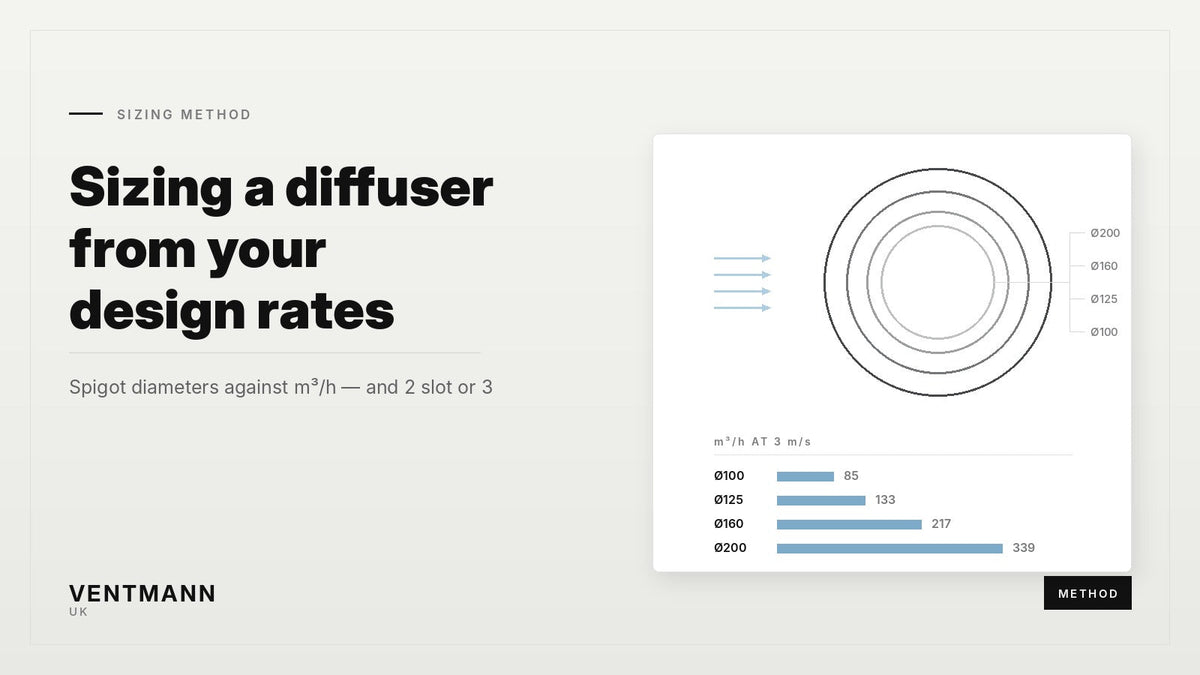
| Spigot | Area | @ 2.5 m/s | @ 3 m/s | @ 4 m/s | @ 5 m/s |
|---|---|---|---|---|---|
| Ø75 | 0.0044 m² | 40 | 48 | 64 | 80 |
| Ø100 | 0.0079 m² | 71 | 85 | 113 | 141 |
| Ø125 | 0.0123 m² | 110 | 133 | 177 | 221 |
| Ø160 | 0.0201 m² | 181 | 217 | 290 | 362 |
| Ø200 | 0.0314 m² | 283 | 339 | 452 | 565 |
All figures m³/h, rounded. Derived from Q = A × v × 3600.
Worked example. A bedroom supply at 13 l/s = 47 m³/h, in a house where the client has already complained about MVHR noise.
At 2.5 m/s a Ø75 carries 40 m³/h — not quite enough. At 3 m/s it carries 48 — adequate but with nothing in hand. Step up to Ø100 and you are at 1.7 m/s, which is silent, or to Ø125 if the duct run is long and you want the pressure drop back. On a GTG box the available knock-outs are Ø75, Ø125 and Ø160 — so the answer here is Ø125, reduced from the branch if necessary with a pressed reducer.
Step 3 — Length and slot count: the real decision
The spigot moves the air to the diffuser. The length and slot count decide what the air does once it gets into the room — how far it throws, how fast it is at head height, and how loud the slot is.
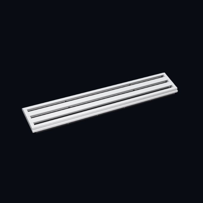
Both Line and Performance Line come in 625, 1000 and 1250 mm, each with 1, 2 or 3 slots. That gives nine combinations and two ways to add free area for a given flow rate: make it longer, or add slots.
They are not equivalent
Adding length spreads the air over a wider arc of the room and shortens throw. Good for wide rooms and for getting a diffuser to line up with a ceiling joint or a lighting run.
Adding slots increases free area without changing the run. It drops face velocity — which drops noise and drops throw — while keeping the architectural line the same width in plan.
So the question "2 slot or 3 slot?" is really "do I need more free area in the same visual length, and am I happy to lose throw?"
When to go 2 slot, and when to go 3
| Condition | 1 slot | 2 slot | 3 slot |
|---|---|---|---|
| Low rate, small room (<60 m³/h) | ✔ default | over-specified | no |
| Mid rate (60–180 m³/h) | only if run is long | ✔ default | if noise critical |
| High rate (>180 m³/h) | no | at 1250 mm only | ✔ default |
| Comfort cooling, occupants below | no | acceptable | ✔ preferred |
| NR 25 or tighter | no | marginal | ✔ preferred |
| Deep room, throw needed | ✔ longest throw | good | throw falls away |
| Extract only | ✔ cheapest adequate | if rate demands | rarely needed |
| Ceiling >3 m | ✔ needs the velocity | good | air may not reach occupants |
The mistake worth avoiding: specifying 3 slots everywhere because it sounds like the premium option. On a high ceiling or a deep room, three slots drop the discharge velocity so far that the air separates from the ceiling early, falls short, and leaves a stagnant zone at the far end. More free area is not automatically better — it is a trade against throw.
Step 4 — Slot gap: 12 mm or 18 mm
Line is offered with a 12 mm or an 18 mm slot gap; Performance Line uses a 20 mm gap with its curved profile. The 12 mm gap is the tighter architectural reveal and reads as a shadow line; the 18 mm gives you half as much free area again for the same run.
Practically: start at 12 mm if the aesthetic matters and the rate is modest. Move to 18 mm when the rate pushes face velocity up and you cannot lengthen the diffuser — usually because the ceiling detail or the joist spacing will not allow it.
Step 5 — Verify against the published data
Everything above gets you to a sensible shortlist fast. It does not replace the performance tables. Before the schedule goes out, put each selection through the Ventmann product selector, which filters the LINE, PLINE and PCIRCLE ranges on:
- design flow rate in m³/h or l/s
- maximum SPLA in dB(A)
- total pressure drop Pt in Pa
- maximum installation length in mm
- number of slots
The full throw (X in metres), pressure drop, SPLA and effective area (Ak) tables for every configuration, supply and extract, are in the technical catalogue.
Step 6 — Carry the sizing through to the plenum
The spigot you chose in step 2 has to exist on the plenum box you specify in step 6. It does not always.
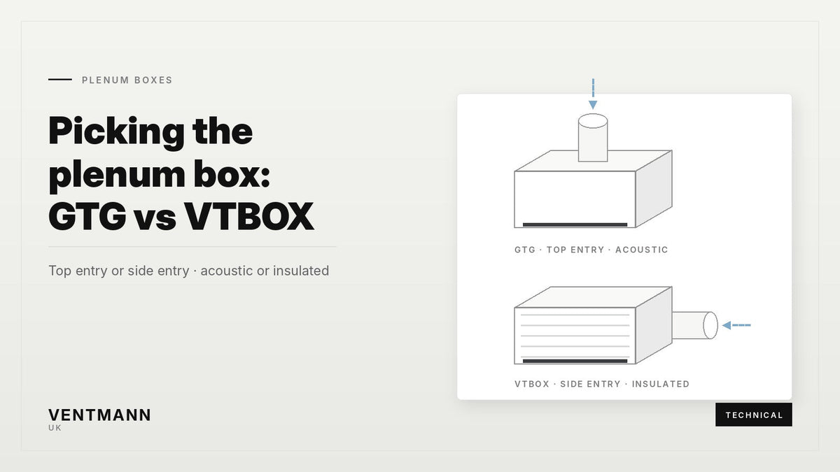
- GTG acoustic box (top entry): Ø75, Ø125, Ø160
- VTBOX thermo box (side entry): Ø125, Ø160, Ø200
If the sizing lands on Ø200, the GTG is out and you are on a VTBOX whichever way the duct arrives. If it lands on Ø75, only the GTG offers it. Width code (A, B or C) must match the diffuser's slot count, and the plenum length must match the diffuser length.
If you are using Performance Circle instead
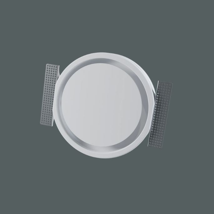
The Performance Circle skips most of this. It connects directly to a Ø125, Ø160 or Ø200 spigot, no plenum, with duties up to around 200 m³/h on the Ø160 and around 300 m³/h on the Ø200. Size the spigot from the table in step 2, choose 1 or 2 slot, and you are done.
The sizing sheet, condensed
- Rate per outlet in l/s → × 3.6 → m³/h
- Choose branch velocity (2.5–3 quiet, 3–4 normal, 4–5 extract) → read spigot off the table
- Choose length from the ceiling layout; choose slot count from rate, noise target and throw
- Choose slot gap: 12 mm for the detail, 18 mm for the free area
- Verify in the product selector against SPLA and Pt
- Match plenum: entry direction, spigot availability, width code, length
Send us the schedule
Give us the room-by-room design rates and the ceiling plan and we will return a sized diffuser and plenum schedule with part numbers, priced. No charge.
Request a free quotation · Open the product selector · +44 (0)1283 240025
Where to go next
- Line vs Performance Line vs Circle — which range to size in the first place
- Picking the plenum box: GTG vs VTBOX — carrying the spigot size through to the plenum
- Classroom ventilation — sizing to an acoustic limit rather than an airflow
- Office diffusers and draughts — the over-sizing trap, and why bigger is not safer
- MVHR diffusers for self-build — the same method on a residential schedule